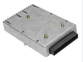
1986-87 and 1989 TTA Grand National Ignition Control Module
25526449 Module 1
ACDelco 24503624
19260720
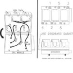
4 connector wires between ignition module and coil pack.
left to right: yellow, green, blue, dark blue.
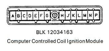
They are labelled (on the connector) as A thru P (with no letter “I” or “O”).
A-G on 1 side, H-P on the other.
The screw that holds the connector to the IM divides these. Do not over tighten when installing the plug!
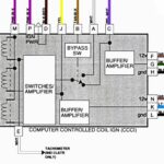
14 connector wires on the ignition module
label – color wire – goes where:
a= white wire, EST, goes to ECM (B4) spark timing output
b= tan-black, bypass, goes to ECM (D5) ignition power bypass output
c= purple-white, ref high, goes to ECM (B5) 12v ref pulse input
d= black-red, ref low ground, goes to ECM (B3) ignition module ground
e= white-tan, tach, goes to tachometer
f= gray-red, crank signal ground, goes to crankshaft sensor “C”
g= black, crank sensor buffer/amp, goes to crankshaft sensor “B”
h= dark green, 12v crank signal power, goes to crankshaft sensor “A”
j= yellow, cam signal for sfi, goes to ECM (A11) fuel injection timing input
k= light blue, cam signal buffer/amp, goes to camshaft sensor “B”
l= black, cam sensor ground, goes to camshaft sensor “C”
m= pink-black, goes to (junction) to CCCI Fuse
n= gray-red, cam sensor 12v signal power, goes to camshaft sensor “A”
p= pink-black, ecm fuse, goes to ECM/IGN fuse (junction, with other things)


